Guitar Pedal Schematics Explained

Wampler PlexiDrive w/ Mods Tagboard Layout Guitar pedals, Diy
A transformer isolated signal splitter that enables hum-free connection of one guitar to more than one amp as well as having a direct output. The circuit is buffered to avoid signal loss. Phase 180 Plus. An update/extension of the Phase 90 with extra stages and controls for the experimenter. Phase 90/180 schematic.

Guitar Effects circuit
The most common resistor value used when making DIY guitar effects pedals is 10K (10,000) Ohms. Throughout all 457 guitar pedal PCBs I analysed, I found that 1,546 10K Ohm resistors were used making this the most common value of resistor for building guitar stompboxes.
Guitars Effect Pedals Amps Distortion pedal Schematic
more than 20000 different guitar effects pedals from more than 3600 brands: vintage, modern, boutique, rare,.

StompBoXed The Guitar Pedal Builders Repository Japanese Guitar
DOD FX-60 DOD FX-64 Icebox DOD FX-67 Turbo Ibanez CS-9 Ibanez PC-10 DualChorus Ibanez SC-10 SuperStereoChorus MXR M-134 Stereo Chorus Nobels CH-D Pearl CH-02 Rocktek Chorus Tel-Ray/Morley CFL Vox 1905 Compressor/Limiter Altec 436C Comp-Amp OFFLINE Dan Armstrong Orange Squeezer DOD 280-A DOD 525 DOD 825 DOD FX-54 Comp/Dist

circuit diagrams guitar effects Photos Circuit Diagrams
Whether you're a complete beginner at building DIY guitar effects pedals or even a complete beginner with electronics in general, I'll help you get started on the path to building your first few pedals. Click here for my ultimate beginners guide to building DIY guitar effects pedals.

Guitar Pedal Schematics Explained
Welcome to Schematics, wiring diagrams and detailed instructions for the best DIY Stompbox effects Projects on the internet. Ready-to-Solder PCBs or Complete Stompbox Kits are available for many of the projects. Contact us if you have any questions. Help Keep Our Site Free For Everyone!
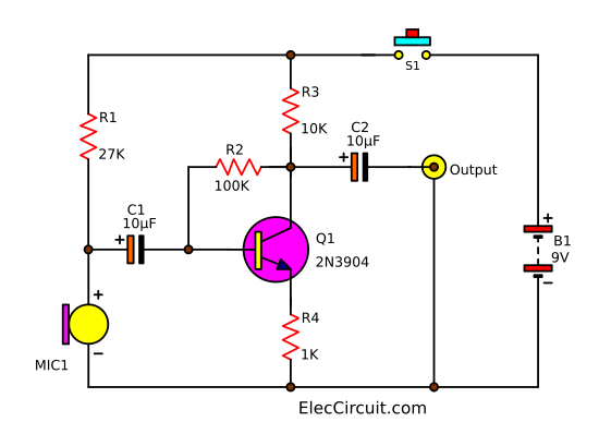
Simple guitar fuzz effect circuit using IC741 Electronic projects
Here are a bunch of schematics, primarily for guitar effects, with some other stuff thrown in. (I use Microsoft Visio for all my technical drawings, including schematics.) Learn more about reading schematics here: From Schematic to Reality Alembic Stratoblaster Schematic Ampeg Scrambler Schematic Apollo Treble Booster Schematic

Simple Guitar Pedal Schematics
Programmable True Bypass Guitar Effect Looper Station Using Dip Switches: I am a guitar enthusiast and a hobbyist player.. In the complete schematics for 8 relays (Fig 1) I added switch transistors (Q1 - Q7, Q9), polarization resistors to set the transistors as On-Off switches (R1 to R16), an 8 switches DIP Switch (S1-1 to S1-8), an on/off.

Coda Effects How to build your first DIY guitar pedal (step by step
The components used in diy guitar pedal schematics can vary depending on the desired effect. Some common components include resistors, capacitors, diodes, transistors, and op-amps. These components work together to shape and manipulate the guitar signal, creating the desired effect.
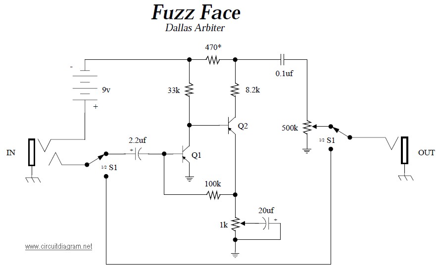
Dallas Arbiter Fuzz Face Circuit Scheme
2. Using a Guitar Pedal Kit We cover several great options for DIY pedal kits above in this article. This is the perfect introduction to creating your effects, because it provides you with the room to be individual, while still sticking to a blueprint for guidance. Guitar pedal kits simplify the process dramatically.

Guitar Effects Schematics & Projects
Guitar FX Layouts Here's a collection of vero (stripboard) and tagboard guitar and bass effect layouts that we have put together covering many classic and popular effects in growing numbers. Many of these have been posted on freestompboxes.org, so check that site out for great discussions on building your own effect pedals.

Guitar Effects Schematics & Projects
Level 4: Design Your Own Pedal Circuits. The ultimate level of building guitar pedals is to build one completely from scratch. Starting with a breadboard (a prototype board), you build up and tweak your circuit design and work your way to your own custom guitar pedal.
spajalica Pravi ljubičasta easy guitar pedal schematics jardindrome
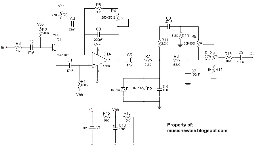
The circuit "starts" with the guitar signal - the V1 shown above this indicates it is a simple audio signal. It goes into the area marked "in", above. The sound then travels through R3 and C23 before coming into the op amp, which is set up as "non-inverting" with soft clipping via diodes. Non-inverting op amps are a key feature of many circuits.
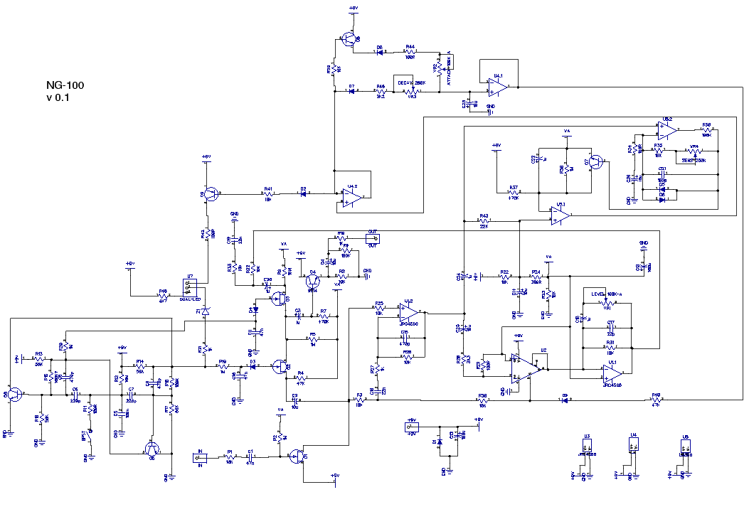
HARLEY BENTON NG100 NOISE GATE GUITAR EFFECTS SCHEMATIC Service Manual
(June 29, 2020) Amplifiers & Headphone Amps Bass Boosters and Volume (Including Tone Boosters) Compressors Direct to Console/PA Distortion Filters, etc. Fuzz Tones Modulation, Echo, etc. Octave Effects Phase Shifters PowerSupplies Reverb Switchers & Routers Tone Controllers/Boosters Six Band Graphic EQ Project Tremolo Wah Wah Other

Guitar Effect Schematic Diagram
Guitar effects circuit diagrams provide a detailed overview of how each element of a custom effects pedal should be connected and configured. By using a schematic, guitarists can ensure that their electronics are properly wired and securely attached to their pedal's chassis. Furthermore, they can make sure that the current flowing through.

A large online repository or library of guitar pedal schematics
Revolutionize your guitar or bass pedalboard with easy-to-build, studio-quality effects inspired by the classics. Get Started. DIY Without Compromise.. Our projects are known for their detailed documentation, including schematics, drill templates, suggestions for modifications, and a parts spreadsheet for easy ordering..
