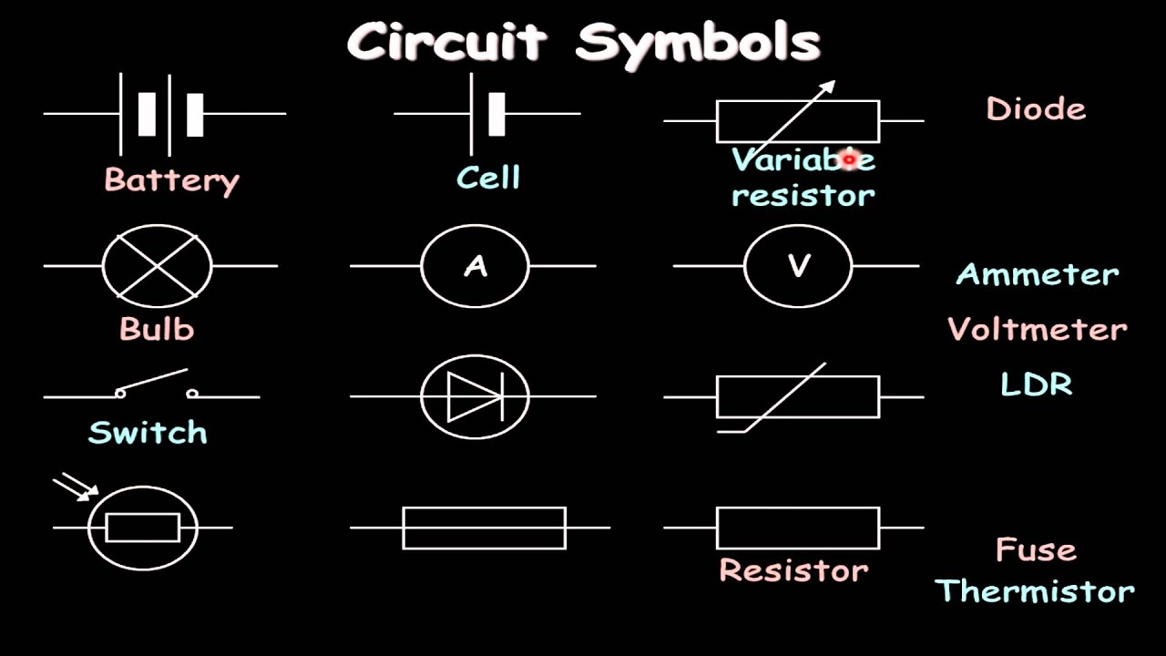
Electrical circuit symbols on white background (Helpful for basic Education & Schools), vector
Guide Electrical & Electronic Circuit Symbols coolguides
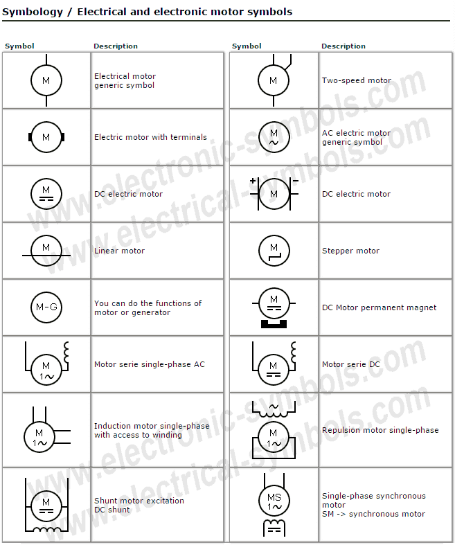
Electric Motor Symbols [ Go to Website ] 1/2 All Electrical & Electronic Symbols in https://www.electrical-symbols.com. electronic devices; electronic components; electronic design; electronic circuits; digital electronics; schematic; ANSI; NEMA; IEEE; IEC Created Date: 9/20/2019 5:38:56 PM.
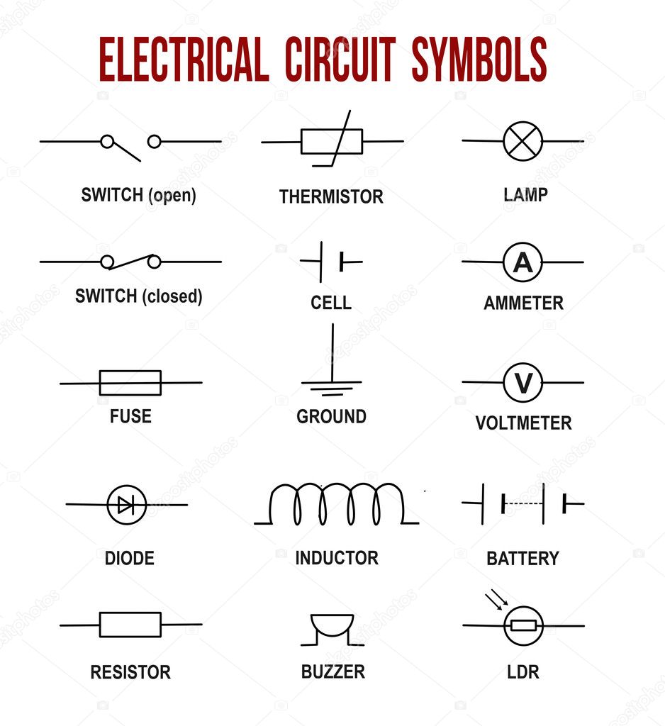
Electrical circuit symbols on white background (Helpful for basic Education & Schools), vector
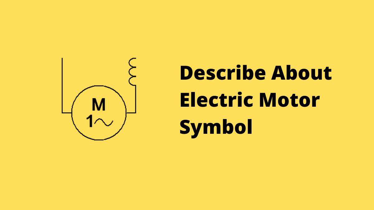
This symbol represents the winding or coil of an electrical motor. The winding inside a motor provides the necessary magnetic field upon excitation through electric current. Series Winding The field winding connected in series to the armature winding of the motor is called series winding.

Schematic Motor Symbol
The schematic symbol for a DC motor is vital in understanding and designing electrical circuits that involve motor control. By using this symbol, engineers and circuit designers can easily identify and analyze the connections and functions of the motor within the circuit.

SynchroMotor Symbols Electrical symbols, Electricity, Symbols
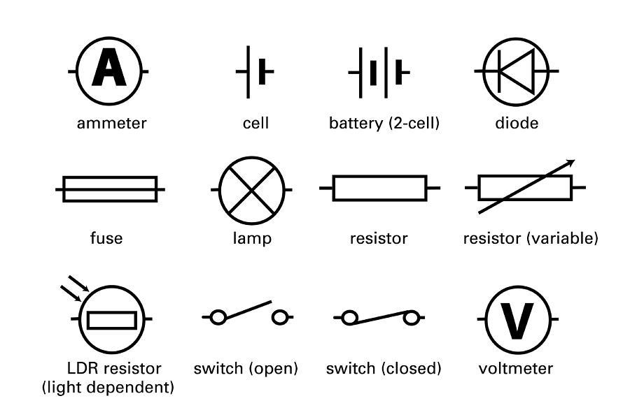
Increasing the light intensity decreases the resistance of a light-dependent resistor. LDRs are often used in sensors found in cameras, light intensity meters and automatic lighting systems. This makes them useful for burglar alarms. Quizzes. Electrical Circuit Symbols Quiz. Back to Lesson.
Electrical Diagrams and Schematics Inst Tools
A system of conducting elements that are designed to conduct electric current for a particular purpose is known as an electric circuit. An electric circuit consists of a source of electrical energy; elements that either transform, dissipate, or store this energy; connecting wires.

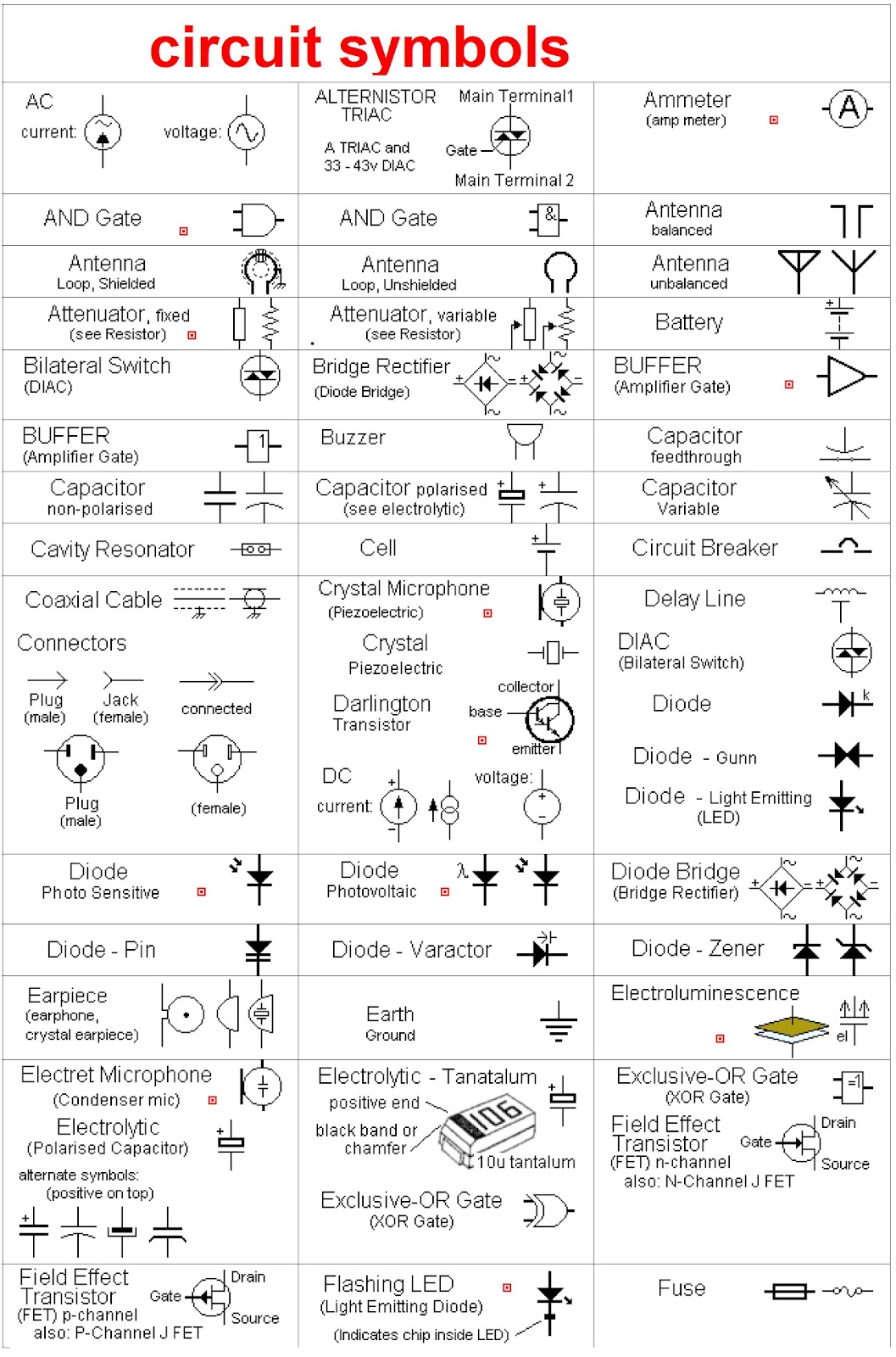
Set Of Electronic Circuit Symbols Stock Illustration Download Image Now Electricity, Symbol
use symbols electrical circuits without use of contacts, static switching control is a method of switching selector two-position three-position two-position selector pushbutton. dc motors wiring connections wye-connected, part winding, reduced-voltage wye/delta, reduced-two-speed voltage horsepower, variable-torque, constant-two-speed single-
Circuit Diagram Symbols Motor
Circuit Symbols The following are the circuit symbols commonly used in motor related schematic diagrams. Panel Wiring Techniques Electrical control panels are available in all shapes and sizes to suit the particular requirements of the situation. These panels may be small as shown in Figure 2, or very large as required to house the necessary.
Discussion On Electric Motor Symbol Voltage Lab
10.1 Motor Control Circuits. The interlock contacts installed in the previous section's motor control circuit work fine, but the motor will run only as long as each push button switch is held down. If we wanted to keep the motor running even after the operator takes his or her hand off the control switch (es), we could change the circuit in a.

Circuit Diagram Symbols Motor
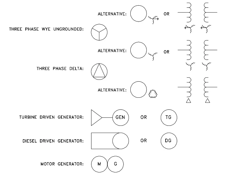
Basic Electrical Symbols. Generator, Motor, Transformer, Battery and Alternator Symbols. Fuse, Switch, Circuit Breaker Symbols. Breaking News. Get Free Android App | Download Electrical Technology App Now! 25% Off on Engineering Designs - Samples; Join Our Official WhatsApp Channel to Get Latest Updates.
Electrical Schematic Symbols Motor Control
Electrical Symbols - MOTOR CIRCUIT BREAKER. Motor circuit breakers are components for connecting, protecting and separating current circuits primarily loads with motors. At the same time, they protect these motors from damage due to blocked starting, overload, short-circuit and single-phase failure in three-phase networks..

Electric Motor Wiring Diagram Symbols Electrical wiring diagram, Electrical symbols
Units & Symbols for Electrical & Electronic Engineering The IET 2016. *Adjective only, as in a.c. motor, d.c. circuit. †As in 3-ph. Supply Ad hoc abbreviations (such as s.s.b. for single sideband) may be employed subject to an initial use in context of the full expression. Some acronyms (e.g. radar, laser) are used as nouns.

Circuit Diagram Symbols Motor
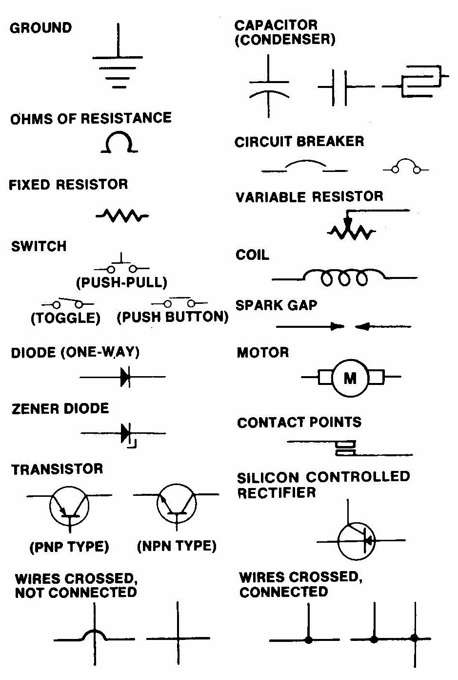
Electrical symbols & electronic circuit symbols of schematic diagram - resistor, capacitor, inductor, relay, switch, wire, ground, diode, LED, transistor, power supply, antenna, lamp, logic gates,.
Circuit Diagram Motor Symbol
A distinction is drawn between: All about wiring of electric motors (photo credit: electronics.stackexchange.com) Block diagram - Simplified representation of a circuit with its main parts. It shows how the electrical installation works and how it is subdivided. Circuit diagram - Detailed representation of a circuit with its individual.

Electric Motors Symbols AC/DC, Single Phase / Three Phase Motors
Electric Motor Symbols Electric motors are electromechanical devices whose function is to transform electrical energy into mechanical energy through electromagnetic interactions. There are other engines ( generators) that produce electricity by exploiting the mechanical energy, such as alternators and dynamos. It may interest you.
Schematic Symbol Motor
The son of a locksmith, Ohm was born on March 16, 1789 in Erlangen, Bavaria (now part of Germany). He was initially educated by his father, who had considerable knowledge of a variety of subjects despite his lack of a formal education, and later entered the Erlangen Gymnasium. By the time he began studies at the University of Erlangen in 1805.
Standard Electrical Circuit Symbols Photograph by Sheila Terry
These two symbols are used to represent fixed resistor. VARIABLE RESISTOR. Rheostat It is a two terminal variable resistor. They are generally used to control the current in the circuit. Generally used in tuning circuits and power control applications like heaters, ovens etc. It is a mini variable resistor.
