AVS VALVE WIRING HARNESS 10', 15', 20' ACCUAIR VU4 VALVE TO STRIPPED
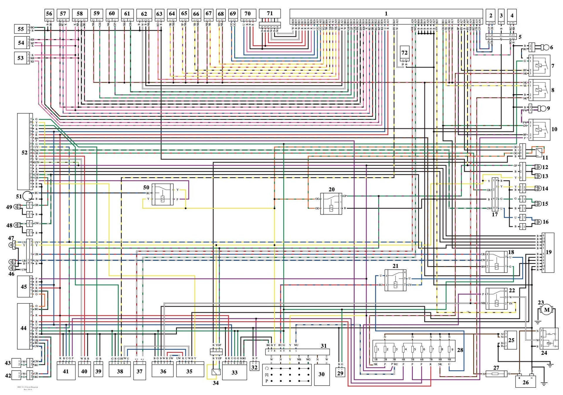
30+ air ride relay wiring diagram PraveenSaumya
EZ Air Ride Dual 444C Wiring Diagram To Tank 12V 40A Relay Do not Use Red Wire To Tank 12V 40A Relay Do not Use Red Wire Pressure Switch TO Keyed power Source (either prong) Fuse. is meant to be a switch for the COMPRESSOR ONLY, NOT VALVES OR MANIFOLDS ETC. Ground Wire— The ground lead on the compressor should not be extended (if possible

Wiring A Switch Box Professional Air Suspension Wiring Diagram
SCHMIDTY. 28471 posts · Joined 2009. #7 · Feb 12, 2015. Deltasig said: I need some assistance. I added the dirty air ride with fast up kit. I want to wire the pressure switch to only work when the ignition switch is on to prevent the system for turning on for some odd reason. I have a 2014 SG need some help on a quick and easy way to wire.

AVS VALVE WIRING HARNESS 10', 15', 20' ACCUAIR VU4 VALVE TO STRIPPED
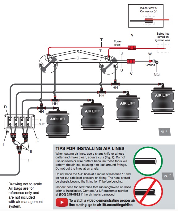
Wiring Diagram for most Manual Operated Air Ride Systems These wiring diagrams cover all "C" Model Viair Compressors as Included with our Manual Air Ride Management Kits Use the Following Diagram for Twin Compressor Setups We recommend all items are installed by a qualified individual (s).
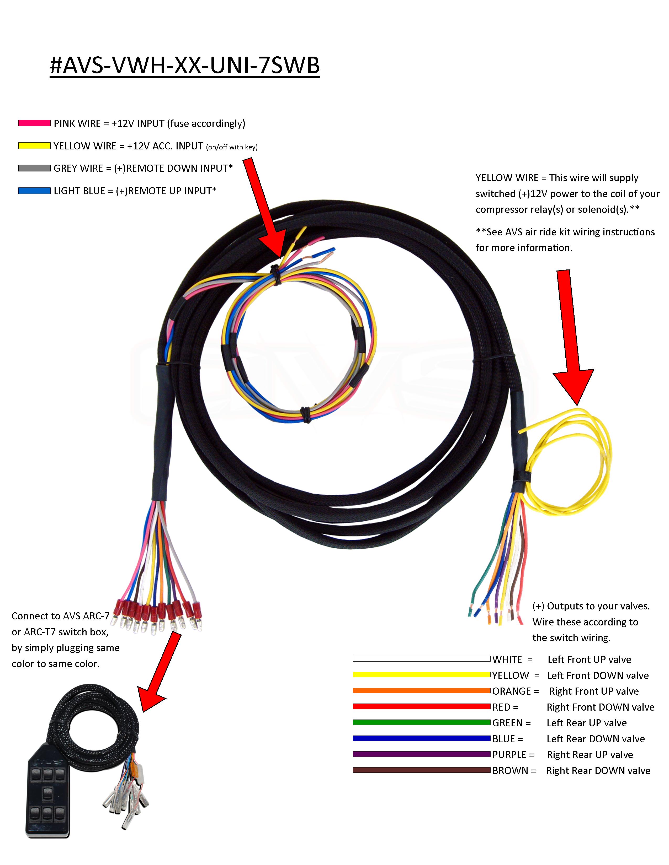
AVS VALVE WIRING HARNESS 10', 15', 20' UNIVERSAL TO AVS 7SWITCH BOX
GREEN AND YELLOW ARE UP AND DOWN SILINOID. 6 WIRE IS CENTER STAND. RED IS POWER. BLACK IS GROUND. TIE BOTH BROWN WIRES TOGETHER. TIE BORTH ORANGE WIRES TOGETHER. BROWN AND ORANGE GO TO THE CENTER STAND ACTUATOR. these are momentary switches for air ride and center stand designed to fit in factory ignition dash for 2014 and up street glide and.

[10000印刷√] avs 7 switch box wiring diagram 310684Avs 7 switch box
The air ride pressure switch wiring diagram is a visual representation of the air ride pressure switch and its connections. It shows the connections between the components of the switch, such as the switches, wires, and terminals. The diagram also shows the power source for the system, such as the battery or an external power supply.

Air Ride Switch Box Wiring Diagram General Wiring Diagram
jibee +1y I am trying to figure out how to wire my switches up for my air ride setup. I have found 3 pin momentary and 6 pin momentary switches. I am confused on how what wires go from where to where and such. I will probably be mounting them in either my console or in one of the dash bezels up around the steering wheel.

Air Ride Switch Box Wiring Diagram Wiring Diagram Schematic
Mounting the Air Tank • The air tank can be mounted anywhere on the vehicle in any position, So long as the sensor is not pointed down. • There is an 1/8" port in the tank that will accept the tank pressure sensor. Mounting the RidePro Air Valves • The valves, like the compressor, are sealed and can be mounted in the same locations.

air ride switch box wiring diagram
Run the switch source like ignition to a relay that relays power from the source to a fused power run for the relays. That switch +12V this way, in the event of a short or problem the fuse will blow and the compressors will stop running. The ignition source will be fine. i may have to draw this up to make sense.

air ride relay wiring
AVS 3 Rocker Switch Box, Black - AVS-ARC-3-BK. Our AVS 3 Rocker Switch Box Black offers total control over your air ride suspension system. Perfect for a 4-valve setup, it lets you switch from front and rear up/down to an all up/down "pancake" with one middle switch. Installation is simple, and wiring diagrams are included. Features:

Air Ride Switch Box Wiring Diagram alternator
The air ride pressure switch wiring diagram is a crucial component in the air suspension system of a vehicle. It is responsible for monitoring the air pressure within the airbags and activating the compressor when necessary to maintain the desired ride height.
air ride switch box wiring diagram HeshamOriane
Basic pressure switch triggered wiring for your air suspension compressors. Relay wiring diagram, for air compressor circuits.
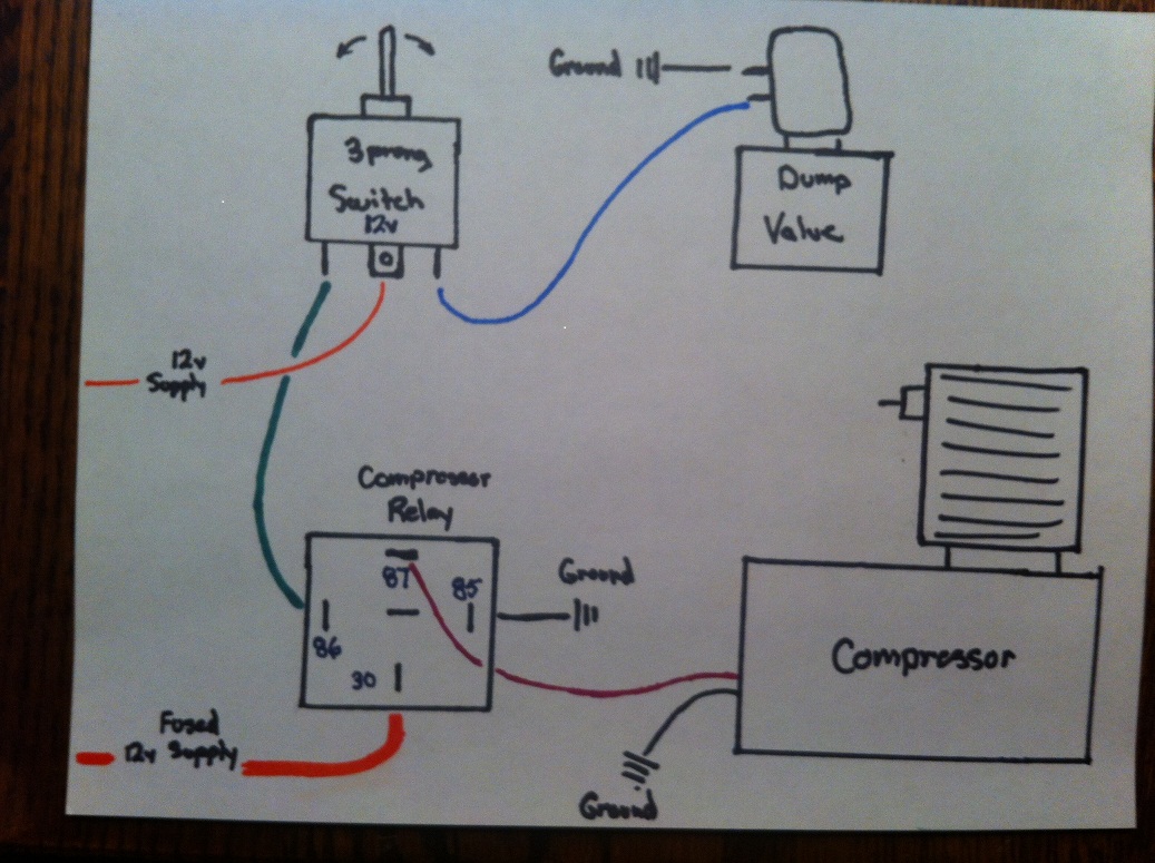
air ride compressor relay wiring diagram
4555 N. Cedar Avenue Fresno, CA 93726 United States of America 559-486-5444

Wiring an AVS switch box with a RIDE HEIGHT CONTROLLER S10 Forum
Our commitment doesn't end with your purchase, in fact, it has only begun. This guide should provide you with the information you need to properly install and set-up your suspension control system. culty or if you have a question that isn't covered in this book, please call our tech department. 812-481-4969.
air ride switch box wiring diagram JedwigaRomy
Paddles & Switches; Valves; Fittings; Air Line; Shocks; Instructions. Elite Manifolds; Compressor Wiring. plumbing and wiring instructions for all of our EZ Air Ride kits. If you need further help, you can find more info below.. (916) 337-2231 [email protected] The Basics. Compressor Wiring Air Tank Setup Air Tank Mounting Spare Air Setup.
Air Ride Switch Box Wiring Diagram General Wiring Diagram
Air Ride Switches; All; Air Ride Switches; 2014 and up air ride and center stand switch pack. $149.95 2000-2013 air ride switch for street glide and roadglide . $29.95 2013 and Down Center Stand Switch . $49.95 2014 SINGLE ON/OFF SWITCH . $39.95 2014 and Up ON/OFF 3 pack . $149.95

10 Air Ride Switch Box Wiring Diagram Activity diagram
FWIW, Home Depot carries a kick-@$$ wire for valves- 18 gauge, 4 conductor, sound and security wire. It's around $.30 per foot, but it's jacketed and shielded, so you won't get any "pops" in your stereo when you hit a switch. Hope that helps! -Phil at FBI. nrskinny +1y.
