7 point plug trailer wiring diagram

7 point plug trailer wiring diagram
The colors for a 4-pin trailer wiring diagram are: White: Ground wire. Brown: Tail/running lights. Yellow: Left turn/brake light. Green: Right turn/brake light. 18-gauge wire is the minimum recommended size for the 4-way plug. This should be used for the lights.
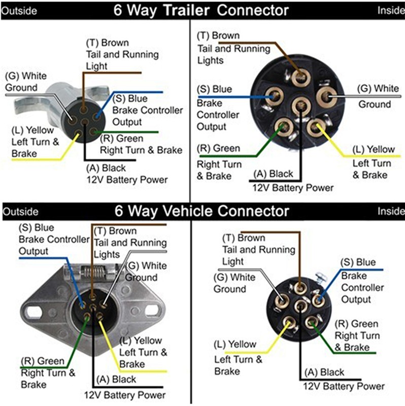
6 Way Flat Blade Trailer Plug Wiring Diagram
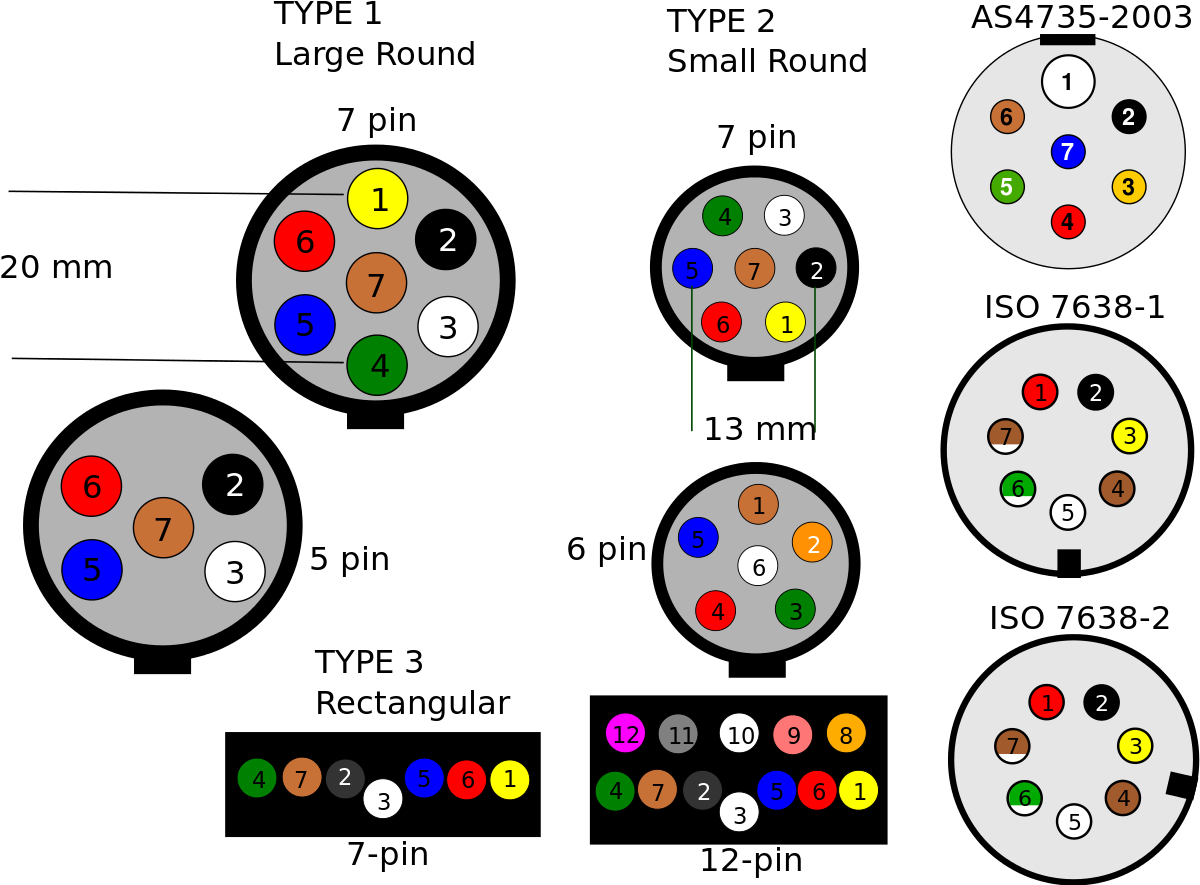
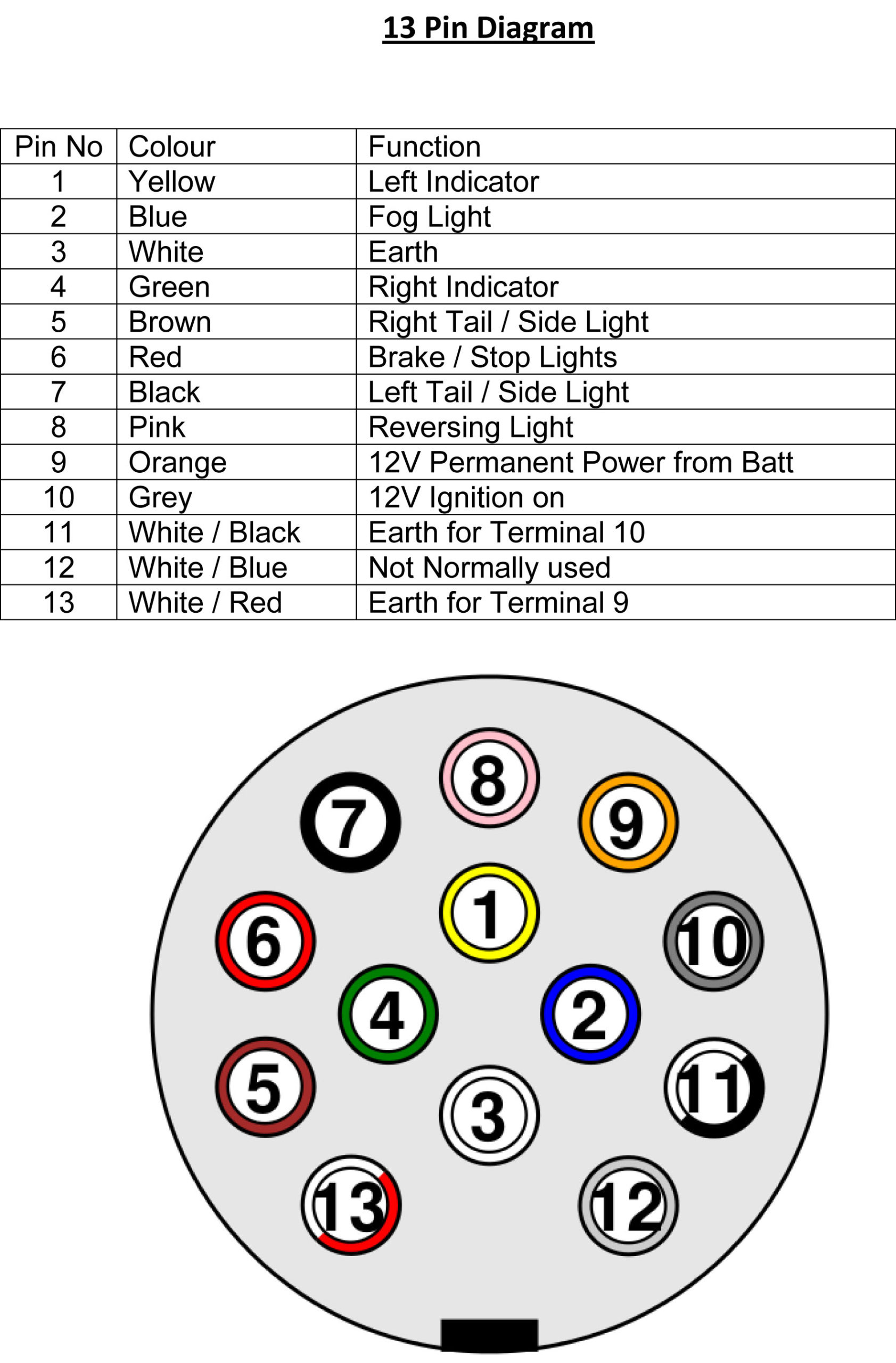
Wiring Diagram Trailer Plugs and Sockets. Narva 7 and 12 pin trailer connectors comply with all relevant ADRs. Flat connectors comply with Australian Standards AS4177.5-2004. Large and small round connectors comply with AS2513-1982 while Heavy duty connectors meet the AS4735-2003 standard as required for vehicles and trailers over 3.5 tonnes.
4 Pin Trailer Wiring Diagram 4 Pin Trailer Connector Wiring Diagram in 2020 Trailer
Use this handy trailer wiring diagram for a quick reference for various electrical connections for trailers. International +1-989-755-0561 Toll-Free 1 -800-358-4751. Login; Account; 0 Cart; Shop By Vehicle. 6-way or 7-way connector. By law, trailer lighting must be connected into the tow vehicle's wiring system to provide trailer running.

Wiring A Trailer & Plug Commercial Trailers Qld Aluminium Machine
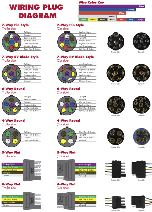
Trailer Wire Color Codes - Colors Coordinate With Trailer Wiring Diagram; Connector Style Pin Function Color Description; 7-Pin: 6-Pin: 5-Pin: 4-Pin: 1: Ground: White: Ground for all trailer electrical functions. 2: Tail Lamps Running Lights Side Markers: Brown: Power for all normally ON lamps. Tail, Running & Side marker lights. 3:

Wiring Diagram For Trailer Hitch Plug
The trailer plug wiring diagram serves as a guide to help you properly connect your trailer's electrical system to your vehicle's system. There are several different types of trailer plugs, but the most common is the 7-pin round plug. This plug is typically used for heavy-duty trailers and provides connections for the ground, tail lights.

Wiring Diagram For 7 Prong Trailer Plug Trailer Wiring Diagram
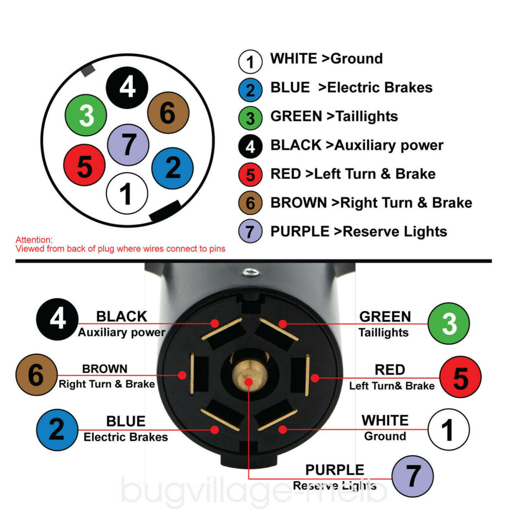
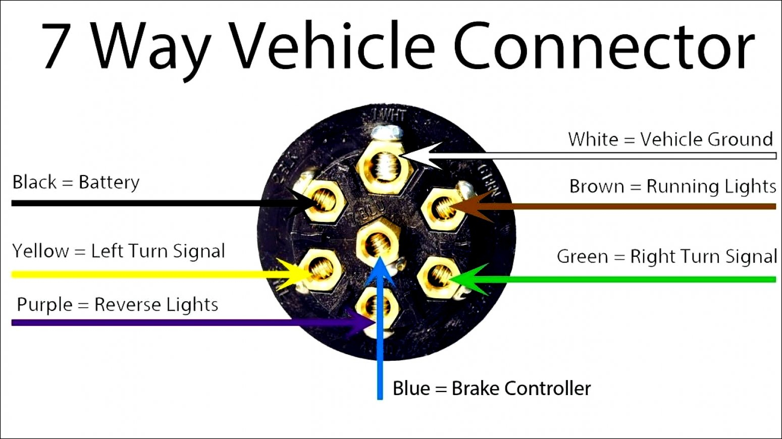
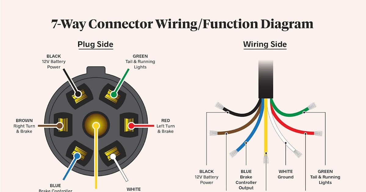
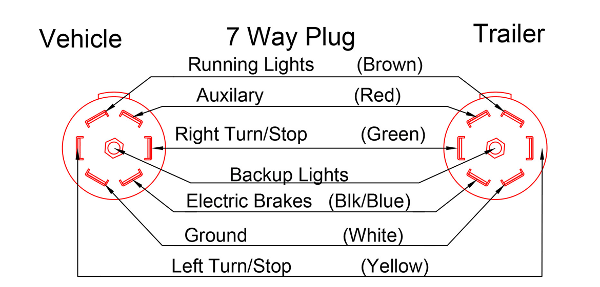
A 7-way plug connects your trailer and tow vehicle and provides the required lights, turn signals, brake power, battery hot lead, reverse lights, and ground. Most of us aren't electricians, but that doesn't mean wiring a trailer or replacing corroded wiring is beyond us. We'll walk you through the wiring process--it's easier than you think!
Wiring For 7 Pin Trailer Plug
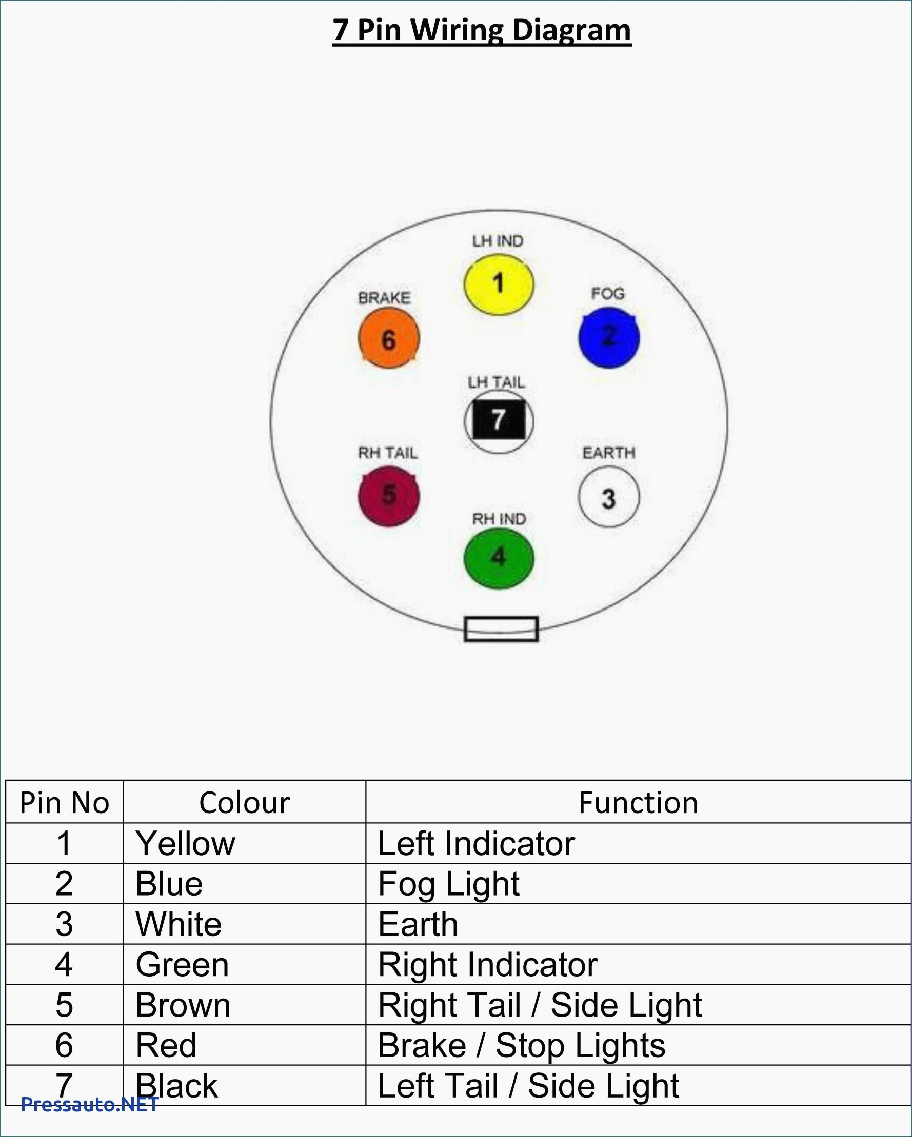
7 Way Plug Wiring Diagram Standard Wiring* Post Purpose Wire Color. S Trailer Electric Brakes Blue GD Ground White A Accessory Yellow This is the most common (Standard) wiring scheme for RV Plugs and the one used by major auto manufacturers today. * Always test wires for function and wire accordingly. This wiring scheme is for reference only.

6 Pin Trailer Connector Wiring Diagram Free Wiring Diagram
The 7-way trailer plug wiring diagram is a valuable tool that can help you easily install the wiring for your trailer's electrical connections. Whether you are a seasoned DIY enthusiast or a beginner, this step-by-step guide will walk you through the process, making it simple and straightforward.
6 Way Trailer Plug Wiring Diagram Wiring Diagram
This trailer wiring guide comes complete with a color coded trailer wiring diagram for each plug type, including a 7 pin trailer wiring diagram, this guide walks through various trailer wiring installation solution, including custom wiring, splice-in wiring and replacement wiring. If your vehicle is not equipped with a working trailer wiring harness, there are a number of different solutions.
7 Pin Trailer Plug Wiring Diagram Flat Wiring Diagram
Trailer Wiring Connectors. Various connectors are available from four to seven pins that allow for the transfer of power for the lighting as well as auxiliary functions such as an electric trailer brake controller, backup lights, or a 12V power supply for a winch or interior trailer lights. Choose a connector that has the required number of.
7 pole trailer plug wiring
The 7-Way Trailer Plug is around 2″ diameter connector that allows an additional pin for an auxiliary 12-volt power or backup lights.. When referencing the 7-Way RV Plug diagram, make sure you are looking at the plug the way the diagram is showing you. Having the wires backward will cause problems. Keep in mind that it isn't always as.
7 Way Trailer Plug Wiring Diagram Ford F250 where to get trailer plug wiring diagram Ford
The 7-pin trailer plug is the most common type used for connecting trailers to vehicles, providing all the necessary signals for lights, brakes, and other electrical components. In this comprehensive guide, we will walk you through the complete wiring diagram for a 7-pin trailer plug, making installation a breeze.
7 Pin Trailer Plug Wiring Diagram Wiring Diagram
Identify the wires: The first step is to identify the wires coming out of your trailer plug. There are typically six wires in a 6 wire trailer plug: ground, brake, tail lights, left turn, right turn, and reverse lights. Use a wire stripper to remove about 1/2 inch of insulation from the ends of each wire. Connect the ground wire: The ground.
Diagrams Technical Information Edwards Trailers Wiring Diagram
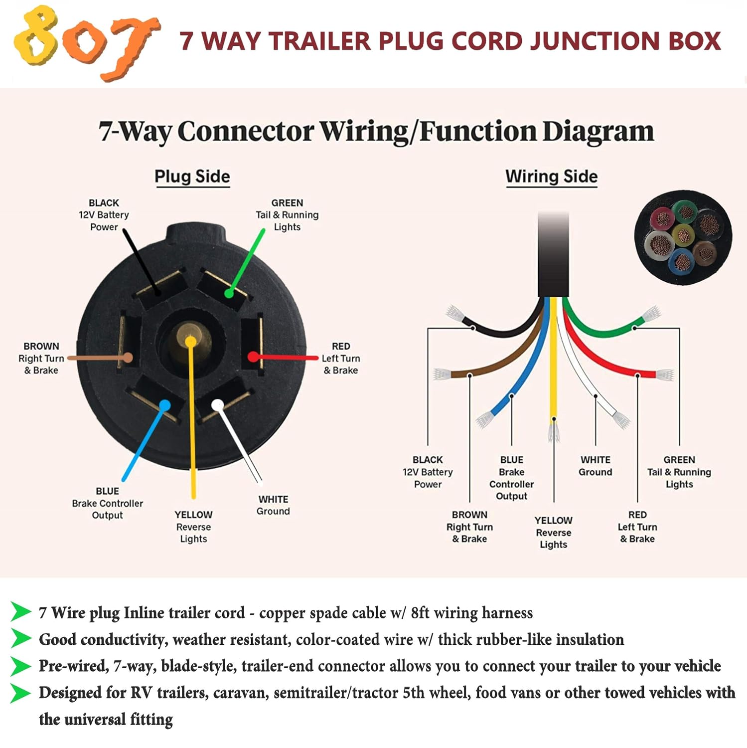
7-way trailer connectors are an essential component for providing transfer of power between a towing vehicle and trailer. Proper wiring of these connectors is important for safe and successful towing. This guide will provide a helpful overview of 7-way trailer plug wiring. Introduction to 7-Way Trailer Plugs The main purpose of 7-way connectors is to.
7 Way Trailer Connector Wiring
The images below show the Common Wiring Guide for Trailer Plugs, Adapters & Sockets. • Illustrations shown represent rear views of connectors. • The photos are what the adapters look like when removed from their housings. • The color key is a breakdown of the wires found in each of their respective systems. Note: The colors illustrated.

7 Way Trailer Connector Wiring
If you have a 4-way plug, add a 5-way with a 4-to-5-way adapter Use a circuit tester to confirm wire function. Step 2: Connect Ground to Vehicle Frame Just like we did on the trailer, we now have to connect the ground on the vehicle side. Attach the white ground wire to a clean, bare metal surface on the vehicle frame.
